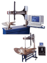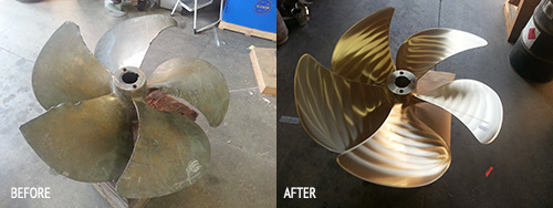
HALE MRI Advanced Technology Electronic 3D Propeller Inspection and Analysis System. The Hale Propeller Measurement Recording Instrument is perhaps the most sophisticated and certainly the most versatile, computerized three dimensional propeller measurement device available. Designed for precise three dimensional position data, these High Resolution Astronomy Grade Optical encoders transmit three dimensional positioning data to the computer. This allows the software to determine and calculate not only pitch but also camber, rake, track, and blade geometry at any point on any blade. The information supplied by these encoders are identical to those used in astronomical telescopes to accurately locate and center a single star. At Olympic Propeller your propeller will be repaired using our Hale MRI High Resolution Analysis System to ISO Class 1 specifications as our shop standard. Upon completion of repair, easy to understand reports are printed, than presented to the customer.

Computer Dynamic Balancing

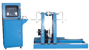
At Olympic Propeller we offer our customers the choice of Dynamics Research 602 Multi-Plane Computerized Dynamic Balance System, or the industry standard vertical plane Static method, using top of the line sealed mechanical bearing rollers, and solid tapered plug type straight shank arbors. A propeller may be in perfect static balance and still not in a balanced state when rotating at high speeds. To correct dynamic unbalance, the use of a true multi-plane dynamic balance analyzer is recommended.
The Dynamics Research Balancing Machine uses a computer and an analog to digital conversion system to gather data and perform the mathematical equations necessary to determine the amount of unbalance in one or two pre-selected planes using the influence coefficient method of balancing. This method provides precise correction indications with minimal cross effect.
The amount of unbalance is displayed digitally on a Color Monitor along with a graphic display of the angle of correction, Unbalance is shown in oz-in, gm-in, gm-mm, mils displacement, or in/sec velocity to name a few.
Both the addition as well as the subtraction position angles on the work piece are indicated on the screen.
The angular position of the work piece is displayed on the Color Monitor in Degrees. This angle is determined using a zero reference mark on the shaft end and an encoder on the motor shaft. This locates the position for precise correction on the work piece.
Background vibration is eliminated by a digital tracking filter that is automatically tuned to rotational speed by the fiber optic phase indicator. All data is collected automatically without operator input. End thrust is limited with an easily adjustable anti-friction end stop which moves with the work piece thereby not restricting motion generated by unbalance.

